Next: About this document ... Up: BOTZILLA PROJECT Previous: 10 PID Contents
Last updated:
$Date: 2003/01/18 18:33:38 $
Some Microchip PIC micro-controllers are programmable once soldered on the application board. This technique, known as ICSP (In-Circuit Serial Programming), has been implemented by Microchip to allow industrial users to program the controller at the very last moment before shipping, thus limiting the number of parts to store (unprogrammed, programmed, on board) and increase flexibility on the assembly line (different software versions per country, special customer tailored versions, evolutions of stocked boards).
For the hobbyist, the advantage on the hardware side is that the programming device is dramatically simplified, and that costly ZIF (Zero Insertion Force) supports, up to 40 pins for some PIC, aren't needed anymore. For the software developer this results in fewer physical manipulations, fastening the code/load/test cycle.
The constraint is that during programming, the PIC must be isolated from the application board regarding power pins (Vcc and gnd), and that one must have access to 2 pins having an alternate use: 2 I/O pins then become programming clock and serial data. Furthermore, the reset pin receive the Vpp programming voltage.
In order to isolate the PIC at programming time on the application board, one can use relays, or jumpers, or may use a dual line of pins connector (18.1). The drawback of a relay is not only its cost but also its size. Jumpers manipulation is tedious and error prone. Whereas the pro of the connector system is a risk-less use and low real-estate consumption on the board.
On this site (http://www.iki.fi/hyvatti/pic/picprog.html)
one can see an unusual use of this technique, in the sense that it's not used to program PIC on application board, but rather to do a dedicated programmer board still usable with all PIC supporting ICSP (pins used for alternate functions are not the same from a Microchip family to another). Nevertheless, the electronic used to link the serial port of a PC to the PIC is mature, cheap, and perform very well.
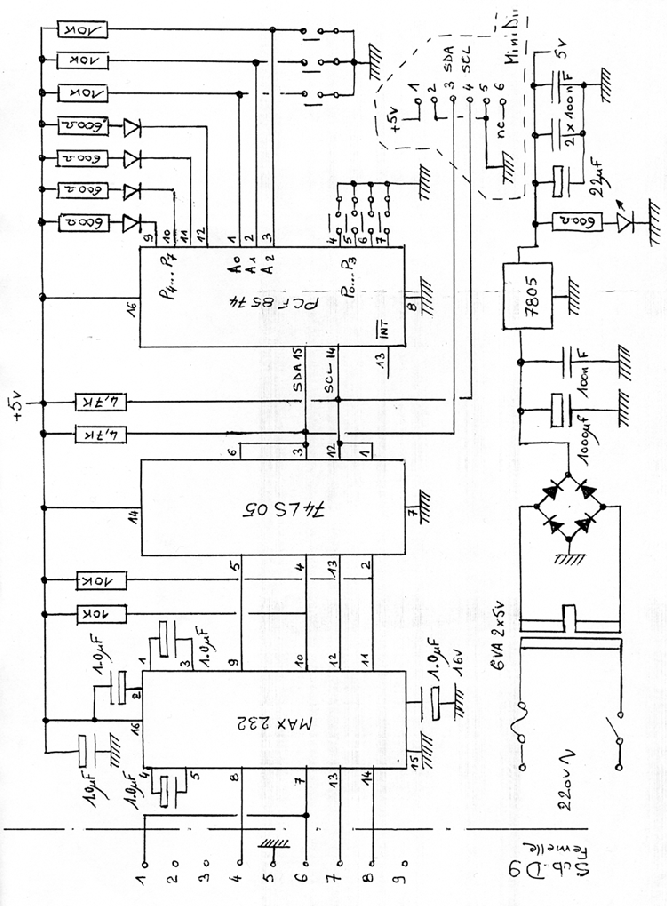
The module contain two parts :
The circuit is build around the PCF8574 (Philips semiconductors) which is a specialized component normally used to provide a 8 bits wide bidirectional extension for microcontrollers. This circuit is available under two ordering numbers , PCF8574 and PCF8574A. The difference between them is the base address which increase flexibility in the use of the bus.
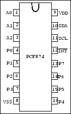
Pin configuration
| SYMBOL | PIN | DESCRIPTION |
| A0 | 1 | address input 0 |
| A1 | 2 | address input 1 |
| A2 | 3 | address input 2 |
| P0 | 4 | quasi-bidirectional I/O 0 |
| P1 | 5 | quasi-bidirectional I/O 1 |
| P2 | 6 | quasi-bidirectional I/O 2 |
| P3 | 7 | quasi-bidirectional I/O 3 |
| Vss | 8 | supply ground |
| P4 | 9 | quasi-bidirectional I/O 4 |
| P5 | 10 | quasi-bidirectional I/O 5 |
| P6 | 11 | quasi-bidirectional I/O 6 |
| P7 | 12 | quasi-bidirectional I/O 7 |
|
|
13 | interrupt output (active LOW) |
| SCL | 14 | serial clock line |
| SDA | 15 | serial data line |
| Vdd | 16 | supply voltage |
There is a Makefile with these files, to compile this program (Linux) type:
make
Because, it's not a real driver (use of ioperm), you have to be root (for Linux user) to use it. This program will test COM1 and COM2 port, and look for a valid PCF target (scan all possible address). When a valid target is found, the program send some bytes to switch ON or OFF the 4 leds connected on the PCF.
botzilla@free.fr , http://botzilla.free.fr/